Introduction
[This essay is mostly superseded by https://guitarvydas.github.io/2021/05/03/Software-Components-101.html and https://guitarvydas.github.io/2021/05/04/Software-Components-101-Connection-Queries.html, etc. I include this essay since it formed a step along my path towards the above articles. Some parts of this essay remain relevant, e.g. Motivating Example and Name Mangling, etc. This essay contains the preamble to the above essays, the motivating example (although, I managed to simplify the example even further in the later essays) and contains queries that are very basic and very simple. It might be helpful to skim this essay before reading the above essays, without getting stuck on any of the details contained herein. This essay also shows a snapshot of my thinking process — continuous divide and conquer. I started out with what looked like a simple problem (line intersection of boxes that have no rotation, and have only vertical and horizontal edges) and, while writing about it, found further simplifications.]
In this essay, I discuss Software Components, my diagrammatic notation for Components and how to manually compile diagrams to code.
I happen to use draw.io for my diagrams, but any diagramming tool (including whiteboards and paper) could be used.
Component Signatures
A Component is defined by its signature:
- a name
- a set of input ports
- a set of output ports.
Notation
Components
A Component is drawn as a rectangle (I used rounded rectangles).
The rectangle contains one (or zero) piece of text which is the "type" of the Component.
I used the word "kind" instead of "type".
If we use the OO analogy, then the "kind" of the Component would be its class. Each Component on a diagram would be an instance of the class.
We don't need to supply a name for the Component because the name is "obvious" from its position on the diagram, and, names are only needed when there are more than one Component of the same kind on the diagram.
In practice, when diagrams are used to represent architecture, instead of code, we tend to have only one of each kind of Component on any one diagram. In this case, the kind suffices to name the Component. The IDE invents unique names for Components. In this bootstrap case, we will name Components by digits between 1 & 9. Generally, we don't need more than 9 Components on a diagram. Diagrams that use more than 9 Components are probably "too busy" to understand. The rule should involve the psychological norm, i.e. 7±2 Components on a single diagram — we expect to use layers, so there might be more than 9 Components in a system but not on a single diagram.
In text, brackets are used to delimit a component's kind, e.g. [a], [a b c], etc.
Ports
Ports have the following attributes:
|
direction |
visibility |
connection |
name |
|
input |
external |
explicit |
<empty> |
|
output |
internal |
implicit |
string |
I use the convention that ports are
- coloured green for input, and
- coloured yellow/red for output.
I use different shapes for port visibility
- bullets[1] denote external ports
- squares, rectangles and circles denote internal ports.
- I use shadows (and text) to denote connection type
- ports with shadows[2] denote ports that can receive implicit connections (dynamic) ; in text, I mark implicit ports with the prefix *
- ports with no shadows (flat, 2D) denote ports that must be connected explicitly (static connections).
Ports can have names. Textually, port names are enclosed in parentheses:
- a port with no name is assigned a number [1-9] by the system (the order is given by the textual signature of the Component)
- a port name can be any text (including spaces, except parenthesis and brackets) allowed by the diagram editing tool.
External Ports
In this example, we have 4 external Ports — 2 input and 2 output.
Their names are "R1", R2", "!" and "#", resp.
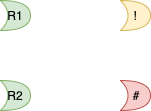
As already mentioned, green Ports are Input Ports. In this case "R1" and "R2" are External Input Ports.
The two External Output Ports are "!" and "#", yellow and red, resp.
By convention (only), I've used the red colour to signify ports that are error ports. In this, simple, example, I collect all errors and send them to a single External Output Port (named "#").
[All four of these ports are explicitly connected. I will discuss explicit vs. implicit later.]
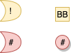
Internal Ports
Example of various internal ports:
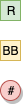
Input Ports
Output Ports
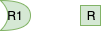
Implicit Connections
Implicit connections "gather" all inputs/outputs from ports with the same name in the immediately enclosed context. For example, a red box with a *# port connects implicitly to all *# ports in the boxes contained in red box. This is shown in Fig. 1
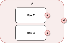
Fig. 1 Implicit Connection Example
In Fig. 1, the outer box contains one *# Port and it collects all data from the *# Ports of Box 1 and Box 2.
Explicit Connections
Connections
Explicit connections are drawn with lines (and arrows). Ports marked as explicit must be connected visually with lines to their sources/sinks.
Composite Component Implementations
Furthermore, Composite Components are described by
- a name
- a set of input ports
- a set of output ports
- an ordered list of child components (their signatures)
- a list of connections.
Concurrency
Components are concurrent by default.
Enclosing components wait for all children to finish before creating outputs.
Finish is defined as
- having empty input queues (no events waiting to be processed)
- being not busy (busy-ness is an issue only in truly concurrent systems ; it is not an issue in systems based on sequential operation (e.g. most current PLs)).
Components can have implicit "reset" inputs. Any value applied to a "reset" input causes the component to immediately stop any work under way and to go back to a known idle (reset) state.
[Implicit reset inputs are meant for optimization — stopping long-running processes].
Special Components
#
[#] components are like exception handlers.
[#] components gather any and all (#) outputs from child components.
As soon as any (#) output is fired from a child component, the child components are reset and the [#] component outputs a trigger message from its (*#) pin.
For debugging, implementation dependent trigger values can be defined, that carry error and debugging information in them. Semantically, the trigger value is taken to be a trigger[3] only and any debug information contained in the trigger is, semantically, ignored.
Any
Any runs all children Components and "stops" after the first one fires its (Any) pin.
Any must wait for all children to subside before processing another event (or going dormant).
Motivating Example
In this essay, I will use a motivating example.
The example is that of determining whether a rectangle intersects another rectangle.
We can do most of this work by looking for line intersections (the 4 edges of one rectangle line-intersecting any of the four edges of another rectangle).
It turns out that general line intersection, e.g. that used by 3D graphics, can be complicated.
For our purposes, we can use simpler algorithms.
Q: How do we document the design rules that we use to determine simple rectangle intersection?
A1: We document our design decisions using layers of diagrams. The diagrams can be compiled to executable code. The diagrams can act as executable comments.
A2: Some of our design rules look like standard type checks. Other design rules usually don't find their way into type systems and/or are hidden by the details of the type rules. An example of this kind of design rule is the fact that we treat only rectangles the have vertical or horizontal edges (i.e. no rotation), to make our checks less onerous and more efficient. We clearly show such rules in the diagrams.
[There is nothing new here. Our design rules could be encoded in a type system. I argue that the diagrams show our design decisions more clearly, in several layers, without losing any of the finer details.]
main - Top Level

Fig. 2 Top Level - main
check
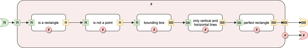
Fig. 3 check
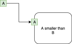
A smaller than B
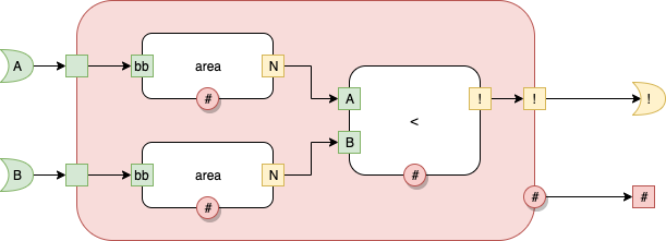
Fig. 4 A smaller than B
A intersects B
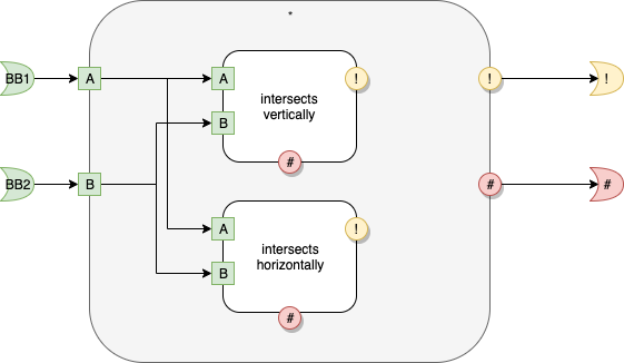
Fig. 5 A intersects B
intersects vertically
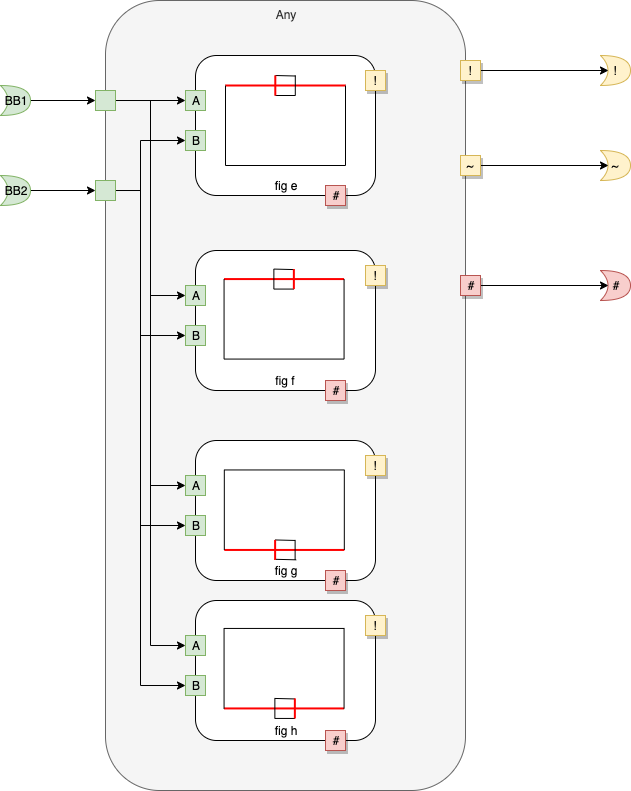
Fig. 6 intersects vertically
Note: I use diagrams as part of the name of the rectangles. The diagrams highlight the intended matching. For example, in the Component called "fig e", matches for the left edge of the smaller rectangle intersecting the top edge of the larger rectangle.
intersect horizontally
asdf
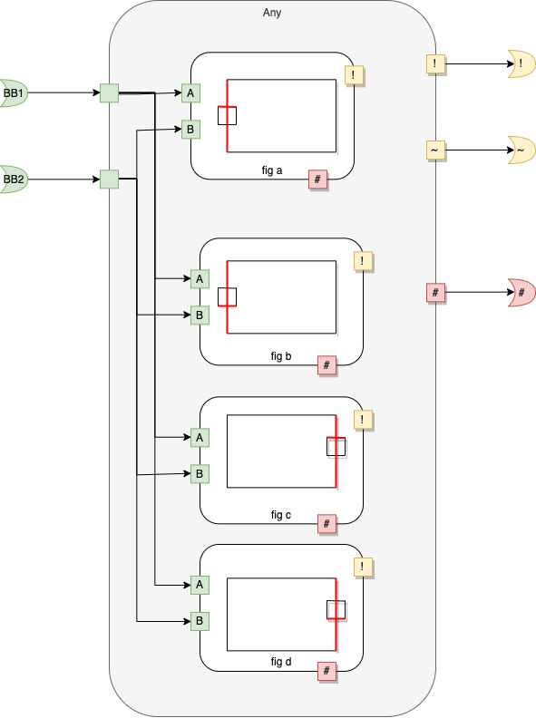
Fig. 7 intersects horizontally
fig a
Fig. 8 fig a
fig b

Fig. 9 fig b
fig c

Fig. 10 fig c
fig d

Fig. 11 fig d
fig e

Fig. 12 fig e
fig f

Fig. 13 fig f
fig g

Fig. 14 fig g
fig h
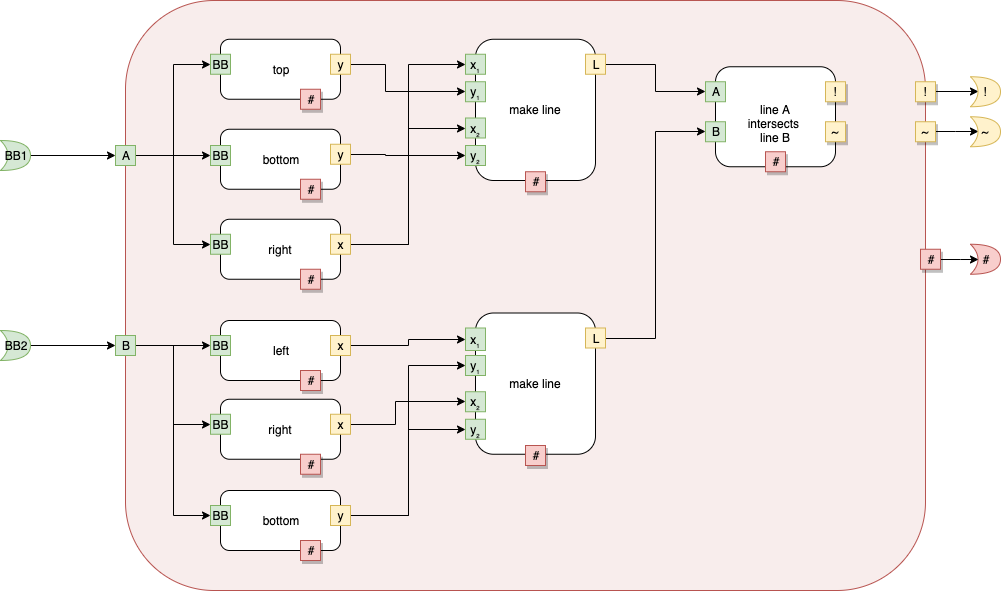
Fig. 15 fig h
Compiling
Let's begin by compiling the "main" component.
We see that main has rectangles within rectangles.
I've used colour and shape to emphasize some concepts.
The Component called "main" consists of 3 levels (0-2), plus the main level.
Each Level can be treated as a compilation unit.
I discuss the levels below.
Overview
main
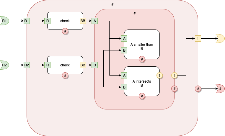
Fig. 16 main top level
We compile this level by subdividing it…
Level 0
Fig. 17 main Level 0
Level 0 is the "top level".
Here we see 2 input ports — named (R1) and (R2) respectively. The input ports are coloured green.
We see 2 output ports — named (!) and (#) respectively. The output ports are not coloured green. The are coloured yellow and red.
Level 1
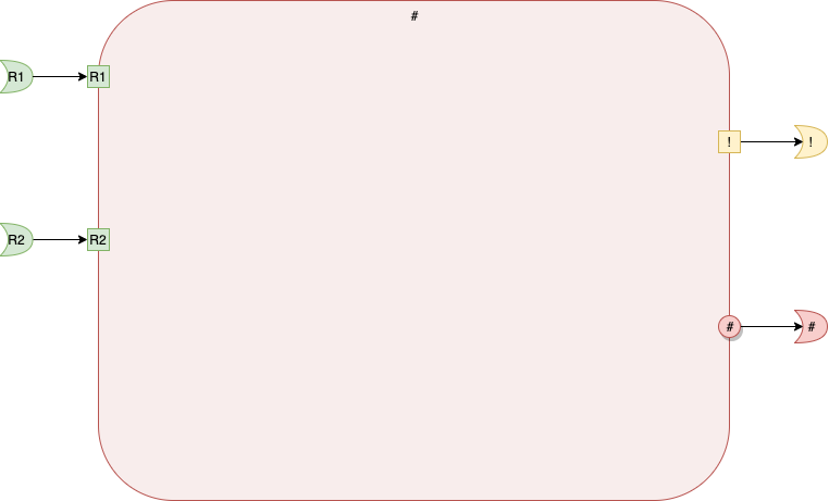
Fig. 18 main Level 1
At Level 1, we see 1 rectangle. The rectangle is named [#] and is coloured red.
By convention, we consider this rectangle to be a Software Component, denoted as [#] in text.
The rectangle has 2 inputs port and 2 output ports. These ports are internal ports and are square or circular in shape.
The output port called (*#) has a shadow. This means that it implicitly connects to all output ports named (*#) at Level 2.
We see that the internal ports are explicitly connected to the external ports using lines (arrows).
Level 2
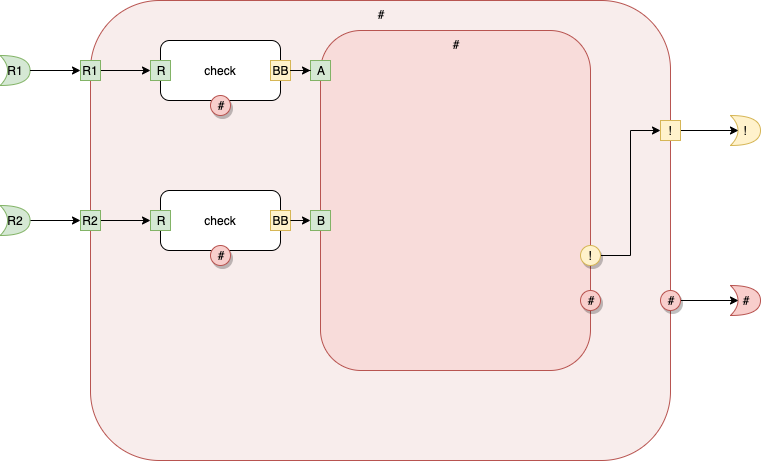
Fig. 19 main Level 2
At Level 2, we see 3 inner components, with kinds [check], [check] and [#], resp.
Because there are two components with the same kind, but different (x,y) coordinates, we (the compiler, the IDE) invent unique names for them.
The 3 components are called [1], [2], and [#].
The first 2 components, [1] and [2] have 1 input port (R) and two output ports, (#) and (BB) each.
The 3rd component, has 2 inputs ports, (A) and (B) and 2 output ports (!) and (#).
Signatures
We're going to proceed in very small, distinct, steps.
In the following discussion of signatures, we will ignore the implementations (the stuff inside of the boxes).
Signature for Level 0
Fig. 17 main Level 0
Level 0 is the "top level".
The signature for Level 0 is
[main] < (R1) (R2) > (!) (#)
{name, inputs, outputs}.
Component names are enclosed in brackets.
Port names are enclosed in parentheses.
Signature for Level 1

Fig. 18 main Level 1
The signature for Level 1 is
[#] < (R1) (R2) > (!) (*#)
Signature for Level 2

Fig. 19 main Level 2
The signature for Level 2 is
[#] < (A) (B) > (*!) (*#)
At the moment, we ignore the signatures for all of the other levels. We deal with only the signature of the Level 2 box — the red box inside the red box on this diagram.
The outer-most red box also contains 2 other components (white) which we will ignore in this part of the discussion.
(The inner boxes are parts of the implementation, not the signature).
Implementations
The implementation deals with "what's inside" of each layer.
We implement connections between components.
Each component implementation contains:
- a list of child components
- connections between children.
(Note that a component can have connections from a component's own input ports directly to its own output ports. This edge-case is handled here, in the implementations).
Here, we deal with implementations only at the diagram SCN level. Components might, also, be implemented as text in other languages, like Python, etc. Those implementations are not described here and vector, via foreign definitions, to the actual implementations in other languages.
Level 0

Fig. 20 main Level 0 Implementation
At this level, there are 2 input ports, 2 output ports and one component.
The implementation at this level is a signature+implementation:
[main] < (R1) (R2) > (!) (#)
{
[
[#] < (R1) (R2) > (!) (*#) { … }
]
[
..(R1) -> [#].(R1)
..(R2) -> [#].(R2)
[#].(!) -> ..(!)
[#].(*#) -> ..(!)
]
}
which contains two lists (denoted by brackets)
- a list of children components (described as signatures, with or without implementations)
- a list of connections.
Components use [] notation, while Ports use () notation. [The result is ugly from a human-readable perspective, but, we want machine-readability — uniformity is the goal, not human-readability.]
In this example, there is one child component called[4] [#]. It has 2 input ports and 2 output ports. All ports belonging to the child are internal, wheres the ports belonging to the top-level are all external. The names of the internal ports overlaps with the names of the external ports — port namespaces belong to the components and must be fully qualified.
Level 1
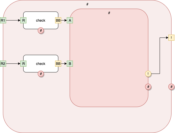
Fig. 21 main Level 1 Implementation
At this level, we write down the signature of Level 1 plus "what's inside" of level 1.
The implementation consists of 3 child rectangles with corresponding signatures, plus a list of connections.
We write this, in text, as
[#] < (R1) (R2) > (*!) (*#)
{
[
[check] < (R) > (BB) (*#)
[check] < (R) > (BB) (*#)
[#] < (A) (B) > (!) (*#)
]
[
.(R1) -> [1].(R)
[1].(BB) -> [#].(A)
[1].(*#) -> ..(*#)
.(R1) -> [2].(R)
[2].(BB) -> [#].(A)
[2].(*#) -> ..(*#)
[#].(*!) -> ..(!)
[#].(*#) -> ..(*#)
]
}
Here, the system has given unique "names" to the two instances of [check]. The names are [1] and [2].
Level 2
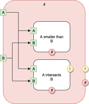
Fig. 19 main Level 2
At Level 2, we see 2 inner components, with kinds [A smaller than B], and [A intersects B], resp.
[#] < (A) (B) > (*!) (*#)
{
[
[A smaller than B] < (A) (B) > (*#) { foreign: "aSmallerThanB" }
[A intersects B] < (A) (B) > (*!) (*#) { foreign: "aIntersectsB" }
]
[
.(A) -> [1].(A), [2].(A)
.(B) -> [1].(B), [2].(B)
[1].(*#) -> ..(*#)
[2].(*#) -> ..(*#)
[2].(*!) -> ..(*!)
]
}
The above says Level 2 contains 2 components [A smaller than B] and [A intersects B].
The components are, also, called [1] and [2], resp.
Component [1] has 2 inputs (A) and (B) and one output (*#).
Component [2] has 2 inputs (A) and (B) and two outputs (*!) and (*#) resp.
Level 2's Port A is connected to [1]'s Port A and to [2]'s Port A.
Level 2's Port B is connected to [1]'s Port B and to [2]'s Port B.
[A smaller than B] and [A intersects B] have implementations that are "foreign", i.e. defined in some other language with the given names (names are the strings).
We could have left the { foreign : … } declarations off. The Component Loader (aka the runtime) loads components — if a component has no implementation at the point of final loading, it is assumed to be foreign. [Q: what are the default rules for name-mangling? Should we delete whitespace, or convert whitespace characters to underscores "_" or, ???. At this moment, I don't have an answer — probably trial and error will be needed.].
Each of the components could have been defined in separate files (along with implementations, if any). The Component Loader checks signatures for compatibility and associates implementations (if any) with each Component. Signatures can be declared multiple times, but only one implementation is allowed.
DRY — Don't Repeat Yourself capabilities are not needed, since the diagram compiler can insert and repeat implementations as needed. If a human-writable/readable notation is required, then DRY could be handled by having a special symbol type that denotes "same as" relationships to other symbols. For example, I toyed with using ^xyz to mean "same as xyz" — which would apply to component names and to port names ; I discarded this notation, since I expect to automatically generate code from diagrams and don't expect to manually write in this notation (other than during bootstrap of the system ; if bootstrapping becomes involved, I might resurrect the ^ notation).
Compilation-1
Putting it all together, we get …
[See https://guitarvydas.github.io/2021/05/03/Software-Components-101.html and follow-ons for details]
Loader
The Loader doesn't declare that any component is foreign, until "the last minute", just before the system is executed.
The Loader incrementally type-checks the signatures and builds a "soup" of valid components and implementations. When a program is executed, it uses the latest versions of implementations for each component.
Versioning
There is no need to version components.
"Versioning" can be implemented by specifying components explicitly in the enclosing layers.
Once a component is deemed to be "working" ("useful"), then no changes are made to that component. Versions of similar components create completely different components, with different names. Components are never versioned, but simply replaced by newer components in newer diagrams. Old diagrams continue to refer to the set of Components that "worked" when the old diagrams were created. New diagrams refer to new Components. (New diagrams can refer, forever, to older Components, too). There is no attempt to replace components in-situ. When a component is upgraded, it is referred-to only by newer diagrams.
Inter-component "type checking" is deferred until "the last minute". The Loader checks to see that all components exist (and are type-correct) before running an app.
Tidbits - Software Components By Example
How: Subject vs. Object
relation(Subject, Object)
Subject == about what?
Object == attribute of Subject under the given relation
e.g.
x(id97,5)
means id97 has an attribute x with a value of 5
I use the convention that Subject is always "bigger" than Object. Subject encloses Object.
Queries
1st thoughts - what can I do, what can I query?
This train of thinking led to aimless experimentation.
Next thoughts — what do I need?
These thoughts led to concrete requirements for queries…
Which Components Are Defined?
Goal: We want a list of all components that have been defined.
PROLOG query
component(C,nil).
PROLOG Rule:
allDefined(All) :-
setof(Defined,component(Defined,nil),All).
Usage:
> swipl
?- consult(pl).
?- consult(queries).
?- allDefined(All).
Example:
?- consult(fb).
true.
?- consult(queries).
true.
?- allDefined(All).
All = ["main", "main #", "main # #"].
?-
All Components?
PROLOG query:
isComponent(C) :-
component(C,nil).
isComponent(C) :-
contained(C,_).
This means: if component(C,nil), then return C, else if contained(C,_), then return C.
Putting it all together, to get a list of unique components (defined or undefined):
allComponents(Set) :-
setof(C,isComponent(C),Set).
example:
?- allComponents(S).
S = ["A intersects B", "A smaller than B", "check", "main", "main #", "main # #"].
?-
Which Components Are Used But Not Defined?
Components that are undefined are ones which are contained, but not declared (with the component() relation).
undefined(C) :-
contained(C,_),
\+ component(C,nil).
?- allUndefined(List).
List = ["A intersects B", "A smaller than B", "check"].
On the full factbase:
?- allUndefined(All).
All = ["area", "bottom", "bounding box", "fig f", "is a rectangle", "is not a point", "left", "less", "line A intersects line B"|...].
The SWIPL REPL elides lists that are too long.
Using write() causes the complete result to be displayed. (One would expect that there is an option, somewhere to set the output line length in the REPL, but I haven't found it, and it is not important enough — this is but a transient need).
?- allUndefined(All),write(user_output,All),nl.
[area,bottom,bounding box,fig f,is a rectangle,is not a point,left,less,line A intersects line B,make line,only vertical and horizontal lines,perfect rectangle,right,top]
All = ["area", "bottom", "bounding box", "fig f", "is a rectangle", "is not a point", "left", "less", "line A intersects line B"|...].
?-
The above output shows "fig f" as being undefined. I did not intend to leave "fig f" undefined — I need to check the input file.
A: Yes, "fig f" was left out of instersects.components.dasl. Copy/paste fixed the problem. I "halt." out of swipl, re-run './run.bash' (to regenerate fb.pl) and re-enter swipl :
?- consult(fb).
true.
?- consult(queries).
true.
?- allUndefined(All),write(user_output,All),nl.
[area,bottom,bounding box,is a rectangle,is not a point,left,less,line A intersects line B,make line,only vertical and horizontal lines,perfect rectangle,right,top]
All = ["area", "bottom", "bounding box", "is a rectangle", "is not a point", "left", "less", "line A intersects line B", "make line"|...].
?-
Now, "fig f" is not in the undefined list.
Do the rest of the undefined Components look OK?
Yes, there are 14 undefined Components. All of them look trivial to build (the heavy lifting was done in creating the diagram, the undefined Components should be trivial).
Missing Signatures
Design Rule check — formerly known as a type check. Look for all components that have no signatures.
[Type checking is not ignored — type checking is made explicit, i.e. the Architect/Engineer must supply the design rule check.]
drcMissingSig(C) :-
component(C,nil),
\+ signature(C,_).
drcMissingSig(C) :-
contained(C,_),
\+ signature(C,_).
drcAllMissingSig(All) :-
setof(C,dcMissingSig(C),All).
?- dcAllMissingSig(All).
All = ["area", "bottom", "bounding box", "intersects horizontally any", "intersects vertically any", "is a rectangle", "is not a point", "left", "less"|...].
?-
In general, it appears that I've not declared signatures for all of the undefined (foreign) components.
After adding signatures, and re-running, I get
?- drcAllMissingSig(All).
false.
?-
Exactly One Signature
If we ask for signatures for a specific part, we sometimes get more than one signature.
?- sig("main # #",S).
S = "< (A)(B) > (*!)(*#)" ;
S = "< (A)(B) > (*!)(*#)".
?-
Why?
Sig() is defined as a rule with 2 alternatives.
PROLOG backtracks through all alternatives.
In this particular case, "main # #" is defined as a component
component("main # #", nil).
and, "main # #" appears in a contained relationship.
PROLOG will backtrack, using the sig rule as we defined it, and show us a signature for the component case as well as a signature for the contained case.
The rule could be rewritten, or it could be written to use the cut (!) operator or we can just use setof to return only the unique values.
In this case, we don't care about efficiency, so we'll take the easiest path — by using the setof operator.
Cut would make the search more efficient (the search would stop after the first successful match), but, we leave that concern to Efficiency Engineers. The goal would be for Engineers to hack on the code to make it more efficient, but to leave the original architecture intact, and, always generate the production version from the architectural version. [How? Using automation. I think that Paul Bennett shows how to do this in his book "Framing Software Reuse",[5] or, by using macros (see M4, awk, etc.)]. Modifying the original architecture effaces history and provinence. Maybe git can be of help here, too.
More Than One Signature
Some Components have more than one signature:
drcMoreThanOneSig(C,Signatures) :-
usig(C,Signatures),
length(Signatures,Len),
Len > 1.
?- drcMoreThanOneSig(C,S).
C = "intersects horizontally Any",
S = ["< ()() > (sb_)(so_)", "< (BB1)(BB2) > (sb_)(st_)(so_)"] ;
C = "intersects vertically Any",
S = ["< ()() > (sb_)(so_)", "< (BB1)(BB2) > (sb_)(st_)(so_)"] ;
false.
(We have already weeded out Components that have 0 signatures, using Missing Signatures)
This check shows us that "intersects horizontally Any" and "intersects vertically Any" have two signatures each. They should have exactly one signature each.
We need to go back to the files to check why this is the case.
A: I added incompatible signatures when correcting Missing Signatures. In fact, I've been learning as I go, and, it turns out that my original signatures were incorrect.
Type Checking Signatures
Note that we have broken type checking down into two sub-tasks:
- signature-to-signature checking
- implementation vs. signature checking.
Using normalization, (1) becomes a simple string compare. Every signature is guaranteed to be of the same form, so a simple comparison of signatures is enough to alert us to problems.
We'll deal with sub-task (2) later.
Contains
What Components does "main" contain?
Single query:
?- contained(C,"main").
C = "main #"
All:
allContained(Parent,All) :-
setof(C,contained(C,Parent),All).
?- allContained("main",All).
All = ["main #"].
Digging down into "main"…:
?- allContained("main #",All).
All = ["check", "main # #"].
?- allContained("main # #",All).
All = ["A intersects B", "A smaller than B"].
Goals
- stand-alone compilation of each diagram
- implement all foreign functions
- do I have enough info to begin implementing?
- what language? what languages?
- 2 languages at once, to keep me honest?
- rough-in all parts
Compiling Main Manually
Let's compile the top-most diagram.
main - Top Level
What do we need to know?
Name Mangling
3) name mangling
We've included spaces (and other special characters) in the names of Components at the architectural level.
Most languages do not allow such characters in names.
We need to adopt a convention on how to re-name architectural components. Ideally, the re-naming should be done by automation (e.g. awk, sed, regex, etc.).
Let's say that all spaces are replaced by underscores "_".
Let's say that all exclamation points (!) are replaced by "_b_" (exclamation points are often abbreviated to "bang"s).
Let's say that all octothorpes (#) are replaced by underscores "o_".
Let's say that all tildes (~) are replaced by underscores "t_".
Let's say that all (*!) are replaced by underscores "sb_".
Let's say that all (*#) are replaced by underscores "so_".
Let's say that all (*~) are replaced by underscores "st_".
I wrote an awk script to mangle names as above, and inserted the script in run.bash.
{
gsub(/\*!/,"sb_",$0);
gsub(/\*~/,"st_",$0);
gsub(/\*#/,"so_",$0);
gsub(/!/,"b_",$0);
gsub(/~/,"t_",$0);
gsub(/#/,"o_",$0);
print $0
}
(Name mangling could have been done in many other languages, my choice of awk is not special. Awk, though, pre-existed many of the other languages).
Components of Main
What Components does "main" contain (recursively)?:
?- allContained("main",All).
All = ["main_o_"].
?- allContained("main_o_",All).
All = ["check", "main_o__o_"].
?- allContained("main_o__o_",All).
All = ["A_intersects_B", "A_smaller_than_B"].
?-
Signatures
What are the signatures for "main" and all of its children?:
?- usig("main",S).
S = ["< (R1)(R2) > (!)(#)"].
?- usig("main #",S).
S = ["< (R1)(R2) > (!)(*#)"].
?- usig("main # #",S).
S = ["< (A)(B) > (*!)(*#)"].
?-
[1] I have switched, since writing this, to using circles to denote external ports (circles are explicit in SVG, whereas bullets are formed by polylines, etc. Bullets can be parsed, but circles require less work).
[2] I have switched, since writing this, to using stroke-width=3 instead of shadows. Stroke-width is more easily handled by SVG.
[3] A trigger is like half of a boolean. It carries no information beyond its own existence. In hardware, these are called "edge triggers".
[4] The red rounded rectangle. It's name is # and we enclose component names in brackets, giving [#] as the component name.
[5] See https://guitarvydas.github.io/2021/01/14/References.html