Software Components 101
This essay introduces some of the concepts of Software Components.
A full discussion of Software Components is fractal and recursive in nature. This essay is an introduction and I choose to skip some of the details.
The key concept is that Components are relative to one another and are asynchronous. These concepts are quite different from those of most modern programming languages, but the concepts are subtle.
I intend to draw components in SVG and I intend to show[1] how to use diagrams, and SVG, as syntax (instead of characters).
Top Level
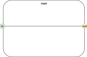
Fig. 1 Basic Component
Fig. 1 shows a basic software component diagram.
This diagram represents the top level of a software Component.
The component's name is "main".
The Component has one Input Port — "in" — represented by the green circle (containing the text "in").
The Component has one Output Port — "out" — represented by the yellow circle (containing the text "out").
The Port "in" is connected to the Port "out" by a line representing the flow of Events from "in" to "out".
[Most lines begin at a green input and end at a yellow output. If we used an arrow, instead of a line, the arrow would point at the yellow output port (the direction of flow). We will see that it is also possible to connect a yellow output to another yellow output and a green input to another green input, later.]
We write the name of the Component as
[main]
the input port as
(in)
and the output port as
(out)
[I.E. Component names are written in brackets, Port names are written in parentheses.]
Nested
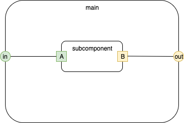
Fig. 2 Nested Component
Fig. 2 shows a component, called "subcomponent" nested inside the component called "main".
Inner input ports are green rectangles.
Inner output ports are yellow rectangles.
External ports are circles, inner ports are rectangles.
The Input Port "in" is connected to the inner Input Port "A".
The inner Output Port "B" is connected to the External Output Port "out".
[This diagram contains two components and a total of two connections.]
Nested Component in a Nested Component
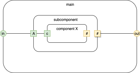
Fig. 3 Component Nested in a Nested Component
This diagram shows 3 components. "Component X" is inside component "subcomponent" and component "subcomponent" is, itself, inside the Component "main".
The component "subcomponent" has an output port called "#". The Output Port has a shadow[2]. The shadow means that the port is connected to all sub-ports with the same name. We write this Port name as (*#). [We prefix the component name with *].
In this diagram, there are 3 Components and 4 connections. 3 connections are explicit (shown as lines) and one connection is implicit ([component X].(#) connected to [subcomponent].(*#)).
Here, we introduce another syntactical point - names can include spaces and any characters except brackets, parentheses and dots. For example the name of the inner-inner component is [component X].
Names are relative. See the section Relative Naming below.
It is easier to think of the above diagram as being subdivided into several layers, eliding the inner details at each layer.
The topmost layer might be thought of as:
.png)
Fig. 4 Component Nested in a Nested Component
whereas the inner layer might be thought of as:
.png)
Fig. 5 Component Nested in a Nested Component
The detail to note is the self [.] is relative, not absolute. Hence, [.] refers to [subcomponent] or to [component X], depending on context.
Copied Component
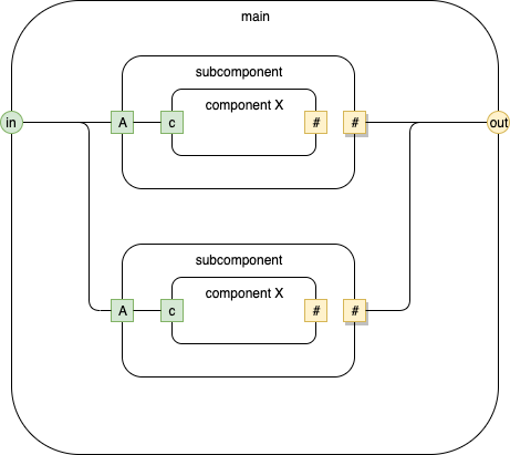
Fig. 6 Copied Component
Fig. 6 shows a simple COPY/PASTE of [subcomponent]. The Component [main] contains two clones of the component [subcomponent].
Relative naming makes this possible and simple and easy.
Composite vs. Leaf Components
Components can contain other components (e.g. composition).
Such components are call composite components.
Composite Components, once invoked, run until all of their children have subsided.
Components that do not contain other components, or are implemented in some other language (other than dasl), are called leaf components.
Leaf Components are like black boxes. When they are invoked, they run to completion (one input event only). We do not "see" — at the dasl level — the inner workings of Leaf Components.
Asynchronous
Components are asynchronous.
Components may only communicate by sending events to their output ports.
Event delivery is, conceptually, not implemented as CALL / RETURN.
Event delivery occurs in two phases,[3] see https://guitarvydas.github.io/2020/12/09/CALL-RETURN-Spaghetti.html).
[It might help to think of closures with input queues and a distinguished routine, called the Dispatcher, that invokes closures that are ready. This concept is not very different from processes and scheduling found in most operating systems, but it can be implemented in a more light-weight manner (there is no requirement for full preemption).]
Run to Completion
Components consume one input event at a time.
Components process each input event to completion before popping another input event from their input queues.
[Note that components can be broken up into pieces which are coordinated by event arrival. Events invoke only one piece of a Component at a time and "running to completion" means that only one piece completes running.]
Ready / Busy
Syntax Details
Dot Syntax
We write a component / port pair as
[ … ] . ( … )
I.E. the Component name is enclosed in brackets, the Port name is enclosed in parentheses and the dot operator joins the two (much like the field operator in most textual OO languages).
Self Component
The self Component has a special name "." and is written as
[.]
Reference to a Port of a self Component looks like
[.].(A)
[We want machine readability first, human readability second. The important point is that Components and Ports have a different syntax which is always the same. The namespace of Input Ports can overlap with the namespace of Output Ports. Syntax is easy to change, if you don't like the above.]
Green vs. Yellow
Green is defined as any colour where the R component is <#80 and the G component is >= #80.
Yellow is defined as any colour where the R component is >= #80 and the G component is >= #80.
Relative Naming
Component names are constructed in a relative manner, by prefixing each component name with its parent component, followed by a space followed by the Component's name.
For example, we would refer to the inner-inner Component of Nested Component in a Nested Component, as
[main subcomponent component X].
This convention does not apply to Port names, since Port names are always internally distinguished by the Component that they belong to, e.g. the Port (c) in Nested Component in a Nested Component is written as:
[main subcomponent component X].(c)
Kinds vs. Names
What we have been calling Component names are actually Component kinds — much like their type or class.
In most cases, there is only one Component of a given kind on a diagram[4].
In the cases where there is more than one Component of a given kind, the components are written as digits, starting at 1, in the order of declaration of the Components (component declarations will be discussed elsewhere).
For example, in Copied Component, the [main] Component has two copies of [subcomponent]. They are written as
[1]…
and
[2]…
(Internally, the components are further distinguished by their (x,y) coordinates and are unique).
Note that [subcomponent] has only one copy of [component X] inside of it, so [component X] is not written in a qualified manner in the implementation of [subcomponent]. [Hopefully this will become more clear with more examples. We are using relative naming, whereas most modern programming languages use absolute naming. All naming and namespacing is relative to the immediate parent Component. Another subtlety is that we are splitting each component up into 3 specifications — signature, children, connections — whereas most modern programming languages attempt to consolidate all code into flat, not relative, specifications]
[1] In a following essay. If one looks at SVG, it should become apparent how to use SVG as syntax. Instead of characters, I use a syntax composed of rects, circles, ellipses, lines and text. I call this DaS (Diagrams as Syntax).
[2] In fact, I will begin using a stroke-width of 3, which is more easily represented and recognized in SVG.
[3] Notably, event receivers are not immediately executed once an event arrives. It is best to think of events as (1) being placed on input queues and (2) Component execution being coordinated by a Scheduler (separate from event delivery).
[4] If this seems anti-intuitive, note that diagrams represent Software Architecture, not Code. In practice, Architectures tend to have only one of each kind of thing on a diagram. (If you are thinking of "+" Components, then you are thinking about Code, not Architecture).