Parsing Diagrams - Ports
Diagram
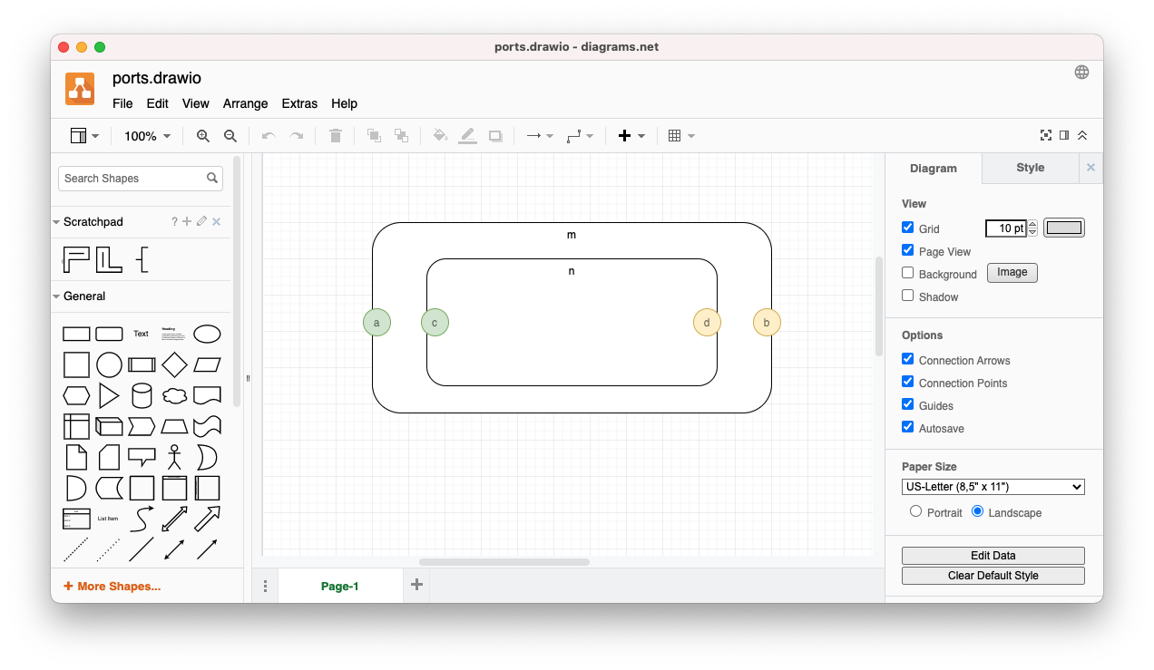
Rectangles represent software components.
Circles represent ports.
- Green circles represent input ports.
- Yellow circles represent output ports.
Port circles are situated on the edges of component rectangles.
[Ports will be connected together as discussed in a future essay.]
[Design Rule checking - aka error checking - is briefly touched upon below, and will be discussed in detail in a future essay.]
Contains Relationships
The diagram editor only knows about rectangles and circles (and colors)1.
We create a compiler phase that associates circles with rectangles.
In this case, we say that a circle is contained by a rectangle if exactly 3 sides of the bounding box of the circle are inside the rectangle.
The code (PROLOG) below emits contains relationships for each circle that meets the above conditions.
Again, to emphasize the point, this is not rocket science, but is grade-school math.
We want something that is easy to write and easy to understand.
Optimization Engineers can rewrite the code if necessary (albeit unlikely with modern hardware).
containsport(R,C):-
    rightsideinsideBB(C,R).
containsport(R,C):-
    leftsideinsideBB(C,R).
containsport(R,C):-
    bottomsideinsideBB(C,R).
containsport(R,C):-
    topsideinsideBB(C,R).

rightsideinsideBB(Circle,Rect):-
    rect(Rect,''),
    ellipse(Circle,''),
    l(Rect,Rl),   t(Rect,Rt),   r(Rect,Rr),   b(Rect,Rb),
    l(Circle,Cl), t(Circle,Ct), r(Circle,Cr), b(Circle,Cb),
    Cl =< Rl,
    Ct >= Rt, Ct =< Rb,
    Cr >= Rl, Cr =< Rr,
    Cb >= Rt, Cb =< Rb.
leftsideinsideBB(Circle,Rect):-
    rect(Rect,''),
    ellipse(Circle,''),
    l(Rect,Rl),   t(Rect,Rt),   r(Rect,Rr),   b(Rect,Rb),
    l(Circle,Cl), t(Circle,Ct), r(Circle,Cr), b(Circle,Cb),
    Cl =< Rr, Cl >= Rl,
    Ct >= Rt, Ct =< Rb,
    Cr >= Rr,
    Cb >= Rt, Cb =< Rb.
bottomsideinsideBB(Circle,Rect):-
    rect(Rect,''),
    ellipse(Circle,''),
    l(Rect,Rl),   t(Rect,Rt),   r(Rect,Rr),   b(Rect,Rb),
    l(Circle,Cl), t(Circle,Ct), r(Circle,Cr), b(Circle,Cb),
    Cl >= Rl, Cl =< Rr,
    Ct =< Rt,
    Cr >= Rl, Cr =< Rr,
    Cb >= Rt, Cb =< Rb.
topsideinsideBB(Circle,Rect):-
    rect(Rect,''),
    ellipse(Circle,''),
    l(Rect,Rl),   t(Rect,Rt),   r(Rect,Rr),   b(Rect,Rb),
    l(Circle,Cl), t(Circle,Ct), r(Circle,Cr), b(Circle,Cb),
    Cl >= Rl, Cl =< Rr,
    Ct >= Rt, Ct =< Rb,
    Cr >= Rl, Cr =< Rr,
    Cb >= Rb.

allPortContains(B):-
    bagof([R,C],containsport(R,C),B).

printAllPortContains:-
    allPortContains(B),
    printPortContains(B).
printAllPortContains.

printPortContains([]).
printPortContains([H|T]) :-
    format("contains(~w,~w).~n",H),
    printPortContains(T).
Port Direction Relationships
Circles colored green are given input relationships.
Circles colored yellow are given output relationships.
The code below creates these relationships. The rule portdirection recognizes the relationships. The rest of the code prints the relationships.
portdirection([P,'input']):-
    ellipse(P,''),
    color(P,"green").
portdirection([P,'output']):-
    ellipse(P,''),
    color(P,"yellow").
allDirections(Bag):-
    bagof(Pair,portdirection(Pair),Bag).

printDirection([]).
printDirection([H|T]):-
    format("portdirection(~w,~w).~n", H),
    printDirection(T).

printAllDirections:-
    allDirections(Bag),
    printDirection(Bag).
printAllDirections.
Design Rules - Error Checks
We want to check for certain error conditions.
General type-checking is insufficient for our purposes.
We use the phrase design rules to mean error checks that are problem-specific.
We want to be able to compose design rule checks and snap them onto the code base.
This issue will be discussed in another essay.
Run.bash
The script run.bash, at this point, is composed of 4 elements
- Infer rectangles as components.
- Infer circles as ports.
- Infer the direction of ports, base on their color (
inputandoutput; green and yellow, resp.) - Perform a design-rule check, quitting the script (the diagram compiler) if any orphan ports are found.
The top-level script is:
#!/bin/bash
./runrects.bash
mv fb.pl rects-fb.pl
./runports.bash
cat rects-fb.pl fb.pl >temp.pl
sort temp.pl >fb.pl

./rundesignrule.bash
and the runports.bash script is
#!/bin/bash
sort ports.pl >fb.pl

./bb.bash >fb-bb.pl
cat fb.pl fb-bb.pl >temp.pl
sort temp.pl >fb.pl

swipl -g 'consult(fb).' \
      -g 'consult(containsport).' \
      -g 'printAllPortContains.' \
      -g 'halt.' \
      > fb-portcontains.pl

cat fb.pl fb-portcontains.pl >temp.pl
sort temp.pl >fb.pl
swipl -g 'consult(fb).' \
      -g 'consult(portdirection).' \
      -g 'printAllDirections.' \
      -g 'halt.' \
      > fb-directions.pl

cat fb.pl fb-directions.pl >temp.pl
sort temp.pl >fb.pl
Reiterating: each phase of the diagram compiler produces a PROLOG-edible fb.pl file.
[Many PROLOG gurus would try to combine all of the phases into one. This would be an optimization, and an obfuscation. It is easier to think of each phase as a single, drop-dead simple entity. The DI (architecture) should retain this simplicity.]
Appendix - Github
https://github.com/guitarvydas/diagram-parsing
See Also
-
The diagram editor edits diagrams. The diagram editor should not know about details of the application, e.g. that rectangles represent components and that circles represent ports. The diagram editor should allow drawing any kind of diagram. Later phases can check the validity of a diagram, much like the phases of compilers for text languages. Knowledge of the application should not be wound into the diagram editor. This is a separation of concerns issue. ↩