Goal
The goal of this sub-project is to build an engine[1] that runs software components.
I try to show how to compile diagrams by hand.[2]
I am trying to capture my design thoughts while they are still fresh. See the roadmap in Roadmap.
I hope to build the engine in:
- Common Lisp
- JavaScript
- Python.
The design for each of the above, is the same, but the details change depending on the language.
I want to capture the design similarities and generate the above engines automatically, if possible.
To do this, I sub-divide the problem and add a new sub-problem:
- pseudo-code in diagram form for the engine.
I think that I'm going to use Ohm-JS and PROLOG to generate code. Let's see…
Prerequisites
See
https://guitarvydas.github.io/2021/05/04/Software-Components-001.html
https://guitarvydas.github.io/2021/05/08/Software-Components-101.html
https://guitarvydas.github.io/2021/05/04/Software-Components-101-Connection-Queries.html
Diagrams
I drew diagrams[3] for the engine.
First, I drew an overview diagram, then I successively added detail. I kept each diagram "simple enough" for me to understand.
As I drew the diagrams, I kept "implementability" and "explainability" in mind.
1. Data and Types
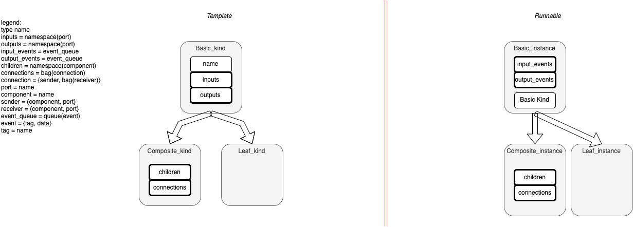
Fig. 1 Data & Types
- Template
- a Template is like a class
- a Template specifies the structure of a Component, but doesn't create an instance
- a Template can be used more than once in a diagrams
- Kind
- a Kind is akin to a Type (Class / whatever)
- I'm using a different name - kind - because the main operation is different than in OO (see below)
- we combine Templates using composition instead of inheritance
- we might want to use the index as a name
- name is either
- template name (if the template is used only once on a diagram), or,
- an index into the ordered bag of children (of this template)
- (we could assign string names to each child, but that's more work than is necessary for this simple example).
- Composite Template
- A Composite is a Template that contains (is composed of) other Templates
- recursive
- a Composite is a Basic Template with 2 additions
- children
- an ordered bag of other Templates
- connections
- connections between child components (and/or self)
- connections can ONLY be made between direct children (and self)
- sender
- one sender per connection
- each sender specifies a connection to zero or more receivers
- each sender is joined to a bag of receivers
- multiple senders can appear to send to the same connection on a diagram
- connections can specify the same bag of receivers, but only one sender per connection
- this looks-like multiple senders sending to the same bag of receivers
- each sender has a name as above (i.e. Template name or index)
- bag of receivers
- each receiver has a name as above (i.e. Template name or index)
- children
- Leaf Template
- a Leaf is the "bottom" of the hierarchy of Templates
- a Leaf is the "termination case" for recursive construction of Templates
- a Leaf is a "black box"
- a Leaf is (probably) implemented in some other language
- Runnable
- a Runnable is the extra stuff needed to instantiate a Template
- since Templates can be used more than once, each Runnable must be unique
- Runnable "points back" to Template for stuff that doesn't need to be copied
- to make a Composite Runnable unique
- need to copy Connections
- fixup all Runnable's Connections to refer to children in Runnable (instances of children)
- Types
- inputs
- outputs
- input_events
- output_events
- children
- connections
- connection
- port
- component
- sender
- receiver
- event_queue
- event
- types boil down to several possibilities:
- a name
- a symbol
- probably implemented as a hashed string
- a symbol
- a collection
- namespace
- bag
- queue
- a tuple
- { ..., ..., ... }
- any
- any of the above
- a name
Note that the "type language" described in the diagram (under legend) should be easy to build in PEG (I like Ohm-JS).
I intend to use the type language in the component diagrams below.
I know that I can implement the type language in Ohm-JS (I've done it before). It simply represents work and "no risk". I will step around this sub-problem for now.[4]
2. Nested Components
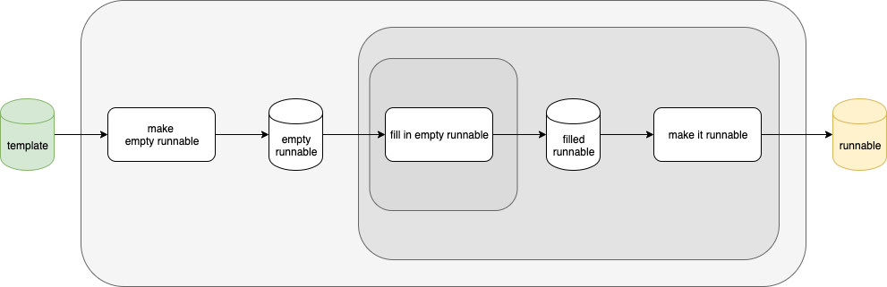
Fig. 2 Nested Components
At first, I draw a rough diagram of how I wish to architect the solution.
The basic operation is: input a template and convert it to a runnable.
I immediately see this solution as 3 nested layers. I jot down the overview — informally — to give myself a roadmap of how I want to solve this problem (the problem is: to build an engine for components and to deliver it in various target languages).
I imagine 3 processes and draw them as rounded rectangles.
I imagine 2 intermediate results and draw them as cylinders.
I draw only the happy path between the processes as arrows.
The gist of this step is to capture/explain my intended architecture while deferring details[5] for later.
3. Add Ports to Nested Diagrams
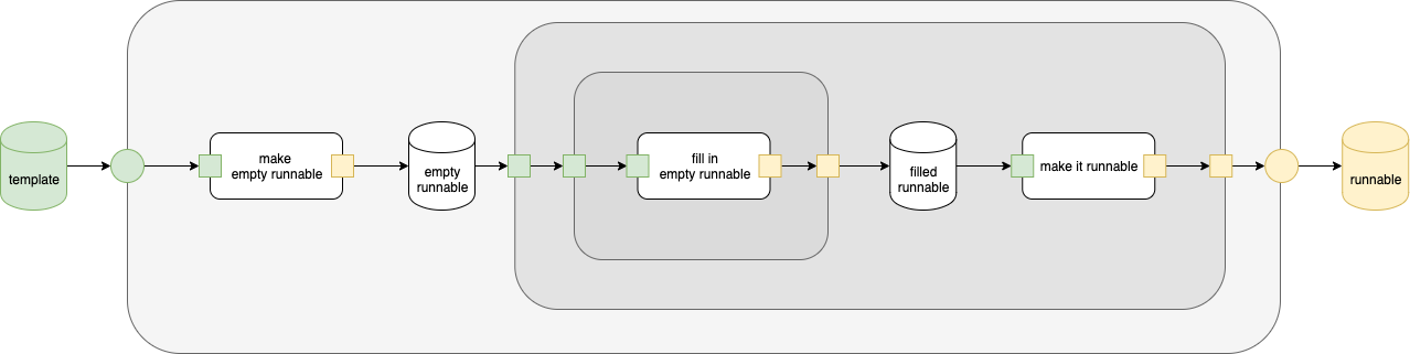
Fig. 3 Add Ports
I embellish the diagram by drawing input and output ports (green and yellow, resp.).
External ports are drawn as circles.
Internal ports are drawn a small squares.
The work, in this step, is minimal, but it makes me ponder the design further. This example is simple. In a more complicated solution, I might change my mind about the design and update the diagrams in this step.
4. Layers
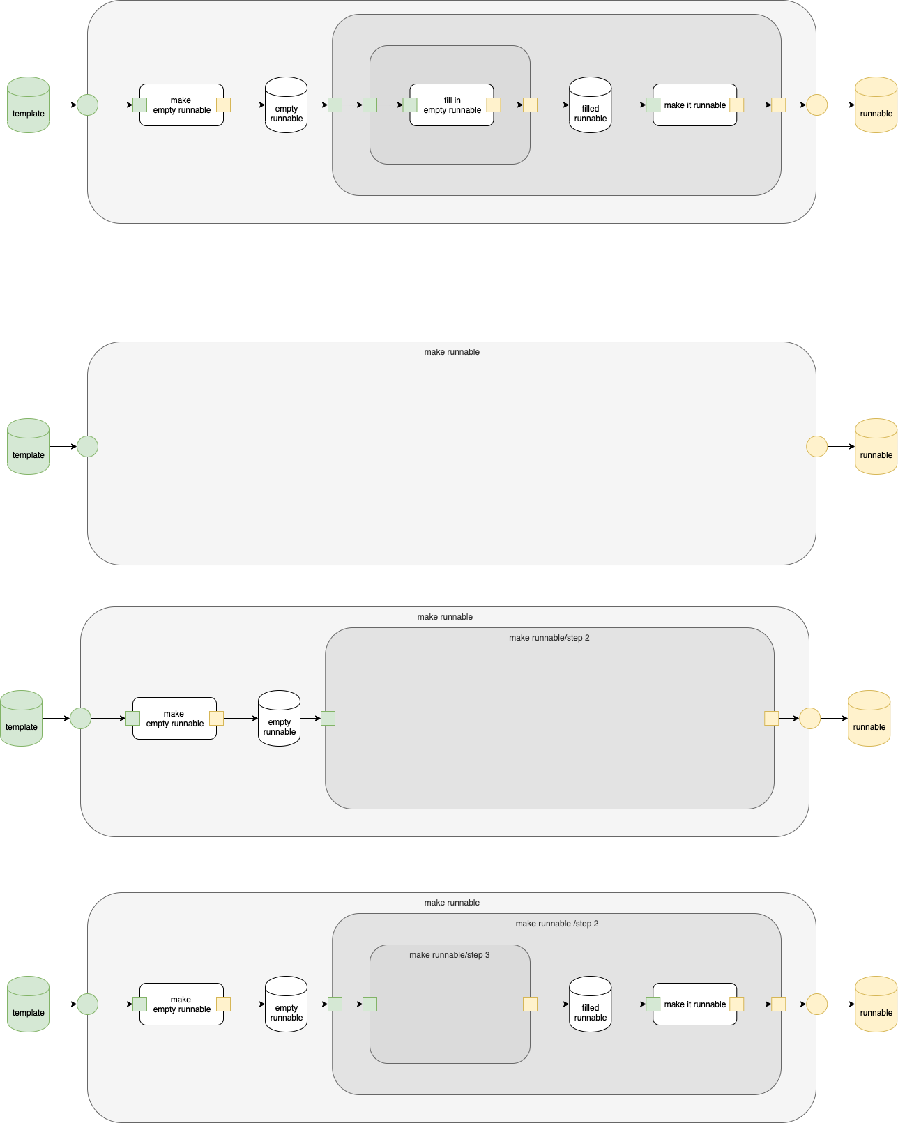
Fig. 4 Layers
I divvy up the design into layers using the previous diagrams as guides. I often do this step implicitly without drawing anything further.
As can be seen, each layer is a black box with input ports and output ports.
5. Rough-in Processes
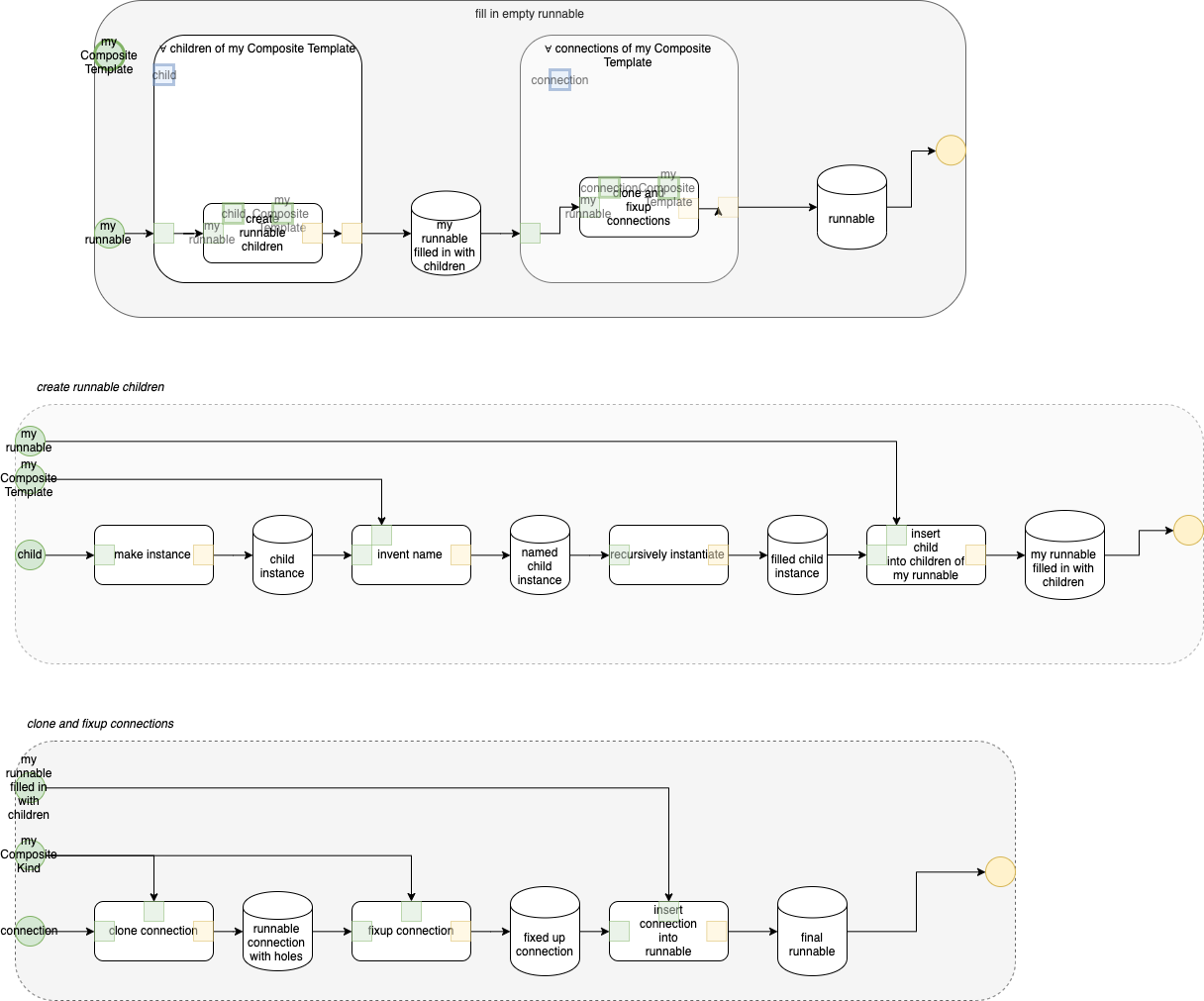
Fig. 5 Rough in
At this point, I am satisfied with the intended solution, so I begin roughing-in the details.
I morphed the top level diagram somewhat — it now contains 2 major process, but still contains 2 intermediate results.
This is engineering, i.e. adding details to the original architecture to make it realizable.
As I consider the details, I add more external ports and flesh out the two main blocks.
I need to remind myself that I am starting out with a template and am trying to build a runnable. I keep these concepts separated, using separate ports and separate connections. When using current programming languages, I would normally fold the architectural concepts (of template and runnable) into a single data structure. In essence, this kind of folding is a premature optimization. I believe that the above diagrams and separation capture my intended approach for all to read (and/or to criticize, I'm not perfect). I want to communicate what I'm thinking and the why's of my intended solution. There might be more than one way to solve this problem, but these diagrams need to show how I choose to solve it.
To enable easier hand-compilation, I've drawn all ports inside the components that own them. Normally, I would draw ports so that they intersect the boundaries of the parent components — intersection and ownership is "easy" for a computer to calculate, but this minor change makes it easier for me to hand-compile the diagrams (as I eye-ball the diagrams). In this case I have only 1 relationship — contains —instead of the two relationships a non-bootstrap compiler would use — contains and intersects. I avoid putting (x,y) coordinates on the diagram as that will slow me down during hand-compilation, but is no problem for a computer.
New invention: the solution that I want to express needs 2 forall operations. I draw these as large components with the ∀ character as the first character in the names and with blue ports signifying the "inputs" from the encompassing forall operation. This might be written as
for child in Template.children { … }
in pseudo-code.
6. Re-Label Rough-in
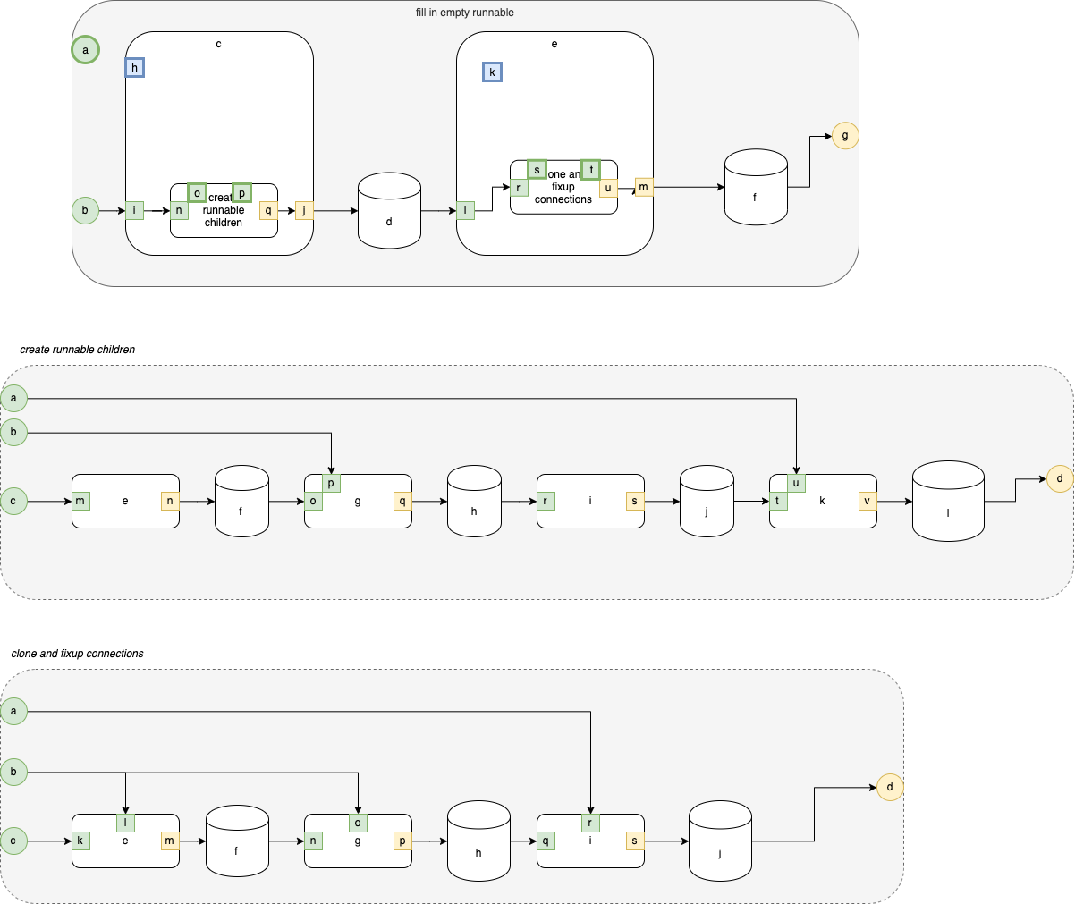
Fig. 6 Re-Labelling
As another aid to hand-compilation, I tag every drawing element with a single-letter symbol. Again, this kind of tagging is not necessary in a fully-automated process, but removes some of the boring and error-prone steps in hand-compilation.
I've tagged all circles, rectangles and cylinders this way.
A fully automated compiler would simply use the graphical objects' IDs and would not require tags.
We can say that the tags are synonyms for the tagged object ID's.
Further
I the next instalment, I will discuss how to convert Fig. 6 into a text file, ready for processing.
Github
https://github.com/guitarvydas/basicdasl/tree/master/pseudo
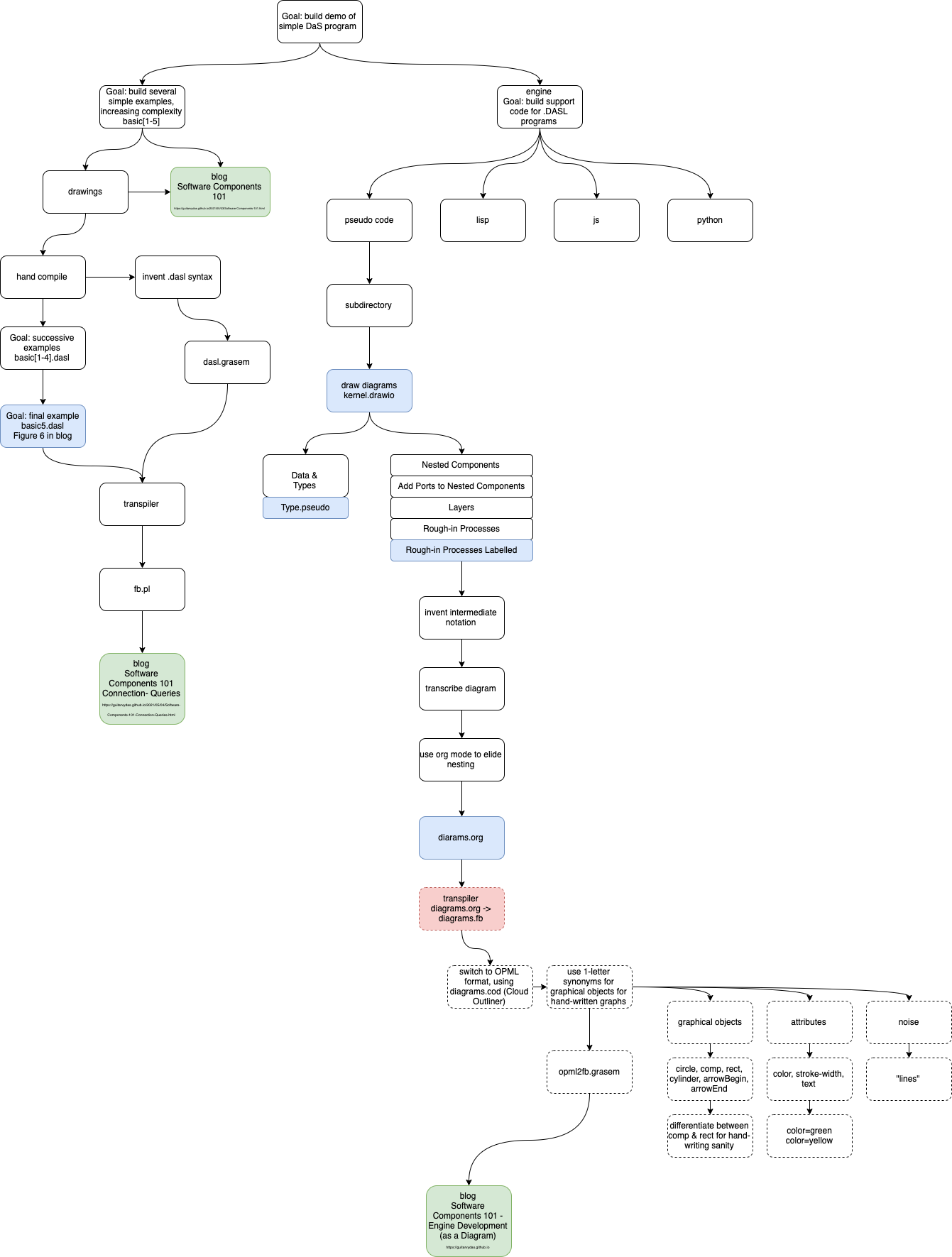
Roadmap
[1] I also call the engine a kernel.
[2] The first step in automating anything is to do it manually. The work should be really boring to do and scream to be automated.
[3] The diagrams are in the file kernel.drawio, under separate tabs.
[4] I will show how to build the type language in another blog. It is just simple, repetitive and boring work. I'll implement it when my brain is fried — there is no point doing it now while I'm still fresh and on a designing-roll. Maybe this is what athletes call "the zone" or "flow state" - I choose to do nothing to break this flow, leaving menial implementation tasks for later.
[5] https://guitarvydas.github.io/2021/03/17/Details-Kill.html